Page 109
4G is a set of requirements, IMT-Advanced. One requirement is 100Mbps speed for a mobile client and Gbps+ for stationary client. LTE-Advanced (Release 10) satisfies IMT-Advanced requirements.
However, companies won the right to market LTE (Release 8) as 4G which is technically 3.9G. So many HSPA+ networks are also marketed as 4G.
LTE standard requires an all IP (Internet Protocol) core network. It is a common successor to both UMTS and CDMA standards.
3GPP history
| Release | Name |
|---|---|
| 4 | Introduced an all IP core network |
| 5 | HSDPA (Downlink) |
| 6 | HSUPA (Uplink) |
| 7 | HSPA+ |
| 8 | LTE |
| 10 | LTE-Advanced |
HSPA+
HSPA+ Release 10 satisfies many of the IMT-Advanced requirements. It’s also cheaper to upgrade existing cellular infrastructure to it. It’s leading the 4G adoption
Page 118
Wi-Fi provides a periodic Delivery Traffic Indication Message (DTIM) sent from the access point. The mobile radio can sleep in between to save battery.
In Wi-Fi, each device sets its own power, usually in the range 30-200mW. In 3G/4G, it is set by the network and can be as low as 15mW. So, WiFi is better for larger data transfer but 3G/4G is good for idle state. Dynamic switching would be the best here.
LTE Radio Resource Controller (RRC)
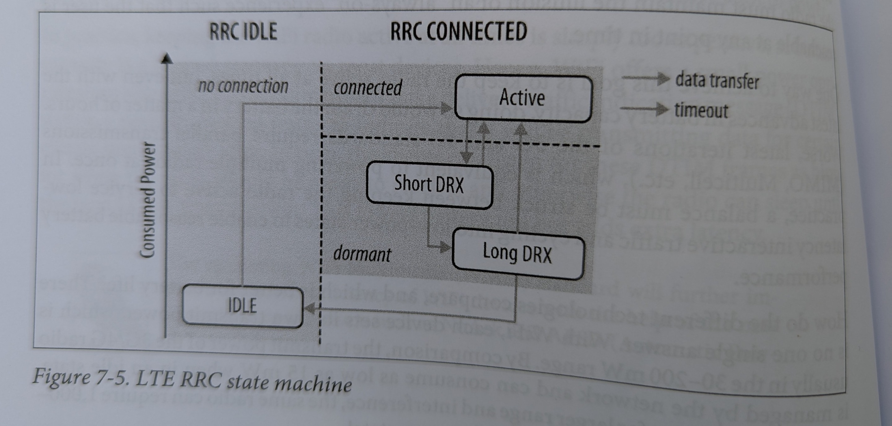
| State | Device State | Network State |
|---|---|---|
| Idle | Low power state (<15 mW), only listening to control traffic | No resources allocated |
| Active | High power state (1000-3500 mW), transmitting or waiting for data | Dedicated resources allocated |
| Short Discontinuous Reception (Short DRX) | Only listens to control traffic | Network context maintained, no resources allocated |
| Long DRX | Same as short DRX, except sleeps for longer | Same as short DRX |
| Idle → Active transition involves issuing a request to the RRC. Can take several round trips. Target of 100ms in LTE and 50ms in LTE-Advanced. |
DRX → Active transition: 50ms in LTE, 10ms in LTE-Advanced
User-plane one way latency is 5ms in both (latency of first hop i.e. to wireless tower)
Active → DRX transition based on timers, like NAT’s removal of port mapping.
Energy Tails
Suppose we want to send some data. Device in Idle state is transitioned to active and we send the data. Then after waiting for timers and cycling through DRX states, the device comes back to idle. A lot of power is wasted in keeping the high power state even when the device is not transmitting.
Periodic transfers on mobile networks are inefficient because of that reason. Better to coalesce them and send less frequently.
End-to-End Carrier Architecture
Looking at the LTE architecture here.

RAN
RAN is the component controlled by the RRC. Each RAN base station (called eNodeB) hosts the RRC
A user has to be moved between towers while maintaining the voice and data sessions (in case the user is moving or his current cell is overloaded). So RAN communicates with the core network to route incoming packets.
The core must know the location of the user, but to save frequent changing of this, a set of towers is grouped into a “tracking area”. User can move between towers in a tracking area with zero overhead.
Core Network (CN)
In LTE, RRC is maintained by the eNodeB, it was maintained at the serving gateway in earlier generations
LTE standard has no latency guarantee for the core network. Latency of packet from eNodeB → SGW → PGW is carrier specific.
Inbound Data Flow
A device can be disconnected from the wireless network (idle state) but it’s long lived TCP connection can be active at the PGW.
Packet at PGW → SGW (queries MME, gets tracking area)
If device is idle, MME sends a paging message to all towers in the tracking area. They broadcast a message to the device to reestablish radio context.
Then tower tells MME → tells SGW which routes the packet to the tower.
Packets get buffered at each state, completely transparently to IP and all above layers. This leads to jitters and high latency for the first packet.